One day when shopping, I found some cylindrical candy tins made from thin aluminum, approximately 1 dm in diameter, 4 cm in height. I realized that they would make pretty nice containers for small electronics projects since the material would be quite easy to work with when drilling. Considering the price is 10 SEK (~1.5USD), this makes for a pretty cheap alternative to using more expensive containers that are intended to house electronics.
One of the first ideas I came up with was to use the tin to house both a small low-wattage speaker, and the amplifier circuitry for driving it. I had some 1-2W 8 ohm speakers laying about and decided to attach one of them to the tin lid.
This called for coming up with a simple circuit for driving the speaker. Since the circuit would operate at a fairly low voltage (9V) most of the signal processing could be done using operational amplifiers, and so I decided to only let the output stage be discrete transistors and the rest would be done in OPamps. Since I had just read about the baxandall tone control circuit in a book by Douglas Self, I decided to include it in the preamp stage of the circuit as well (along with a master volume control of course).
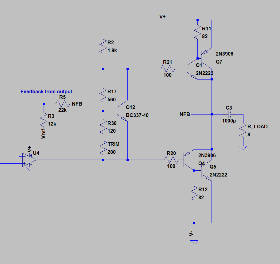
 Shown above is the output stage and its controller OPamp. The output stage is a traditional sziklai-pair (or complementary pair) configuration. Since the operation is single ended, a large coupling capacitor is present at the output. To bias the transistors with a minimum of crossover distortion, a trimpot and a Vbe-multiplier is used.
The feedback network gives a gain of +2 roughly, which for a 1Vrms input gives an output power of 2/8 = 0.25W into an 8 ohm speaker (which is the power rating of the speaker I used).
It should be noted that the output stage is a bit overkill, most likely you could skip the driving transistors since the output currents are quite small anyway and the distortion generated by the base currents won’t be that bad. And to save some more coins, the bias network could be replaced by simply a single diode. This would bias it pretty far into the class B region with substantial crossover distortion, but the bad acoustics of the speaker and the tin can will probably thoroughly dominate the circuitry in terms of diminished sound quality anyway 😉
The preamp is shown below:
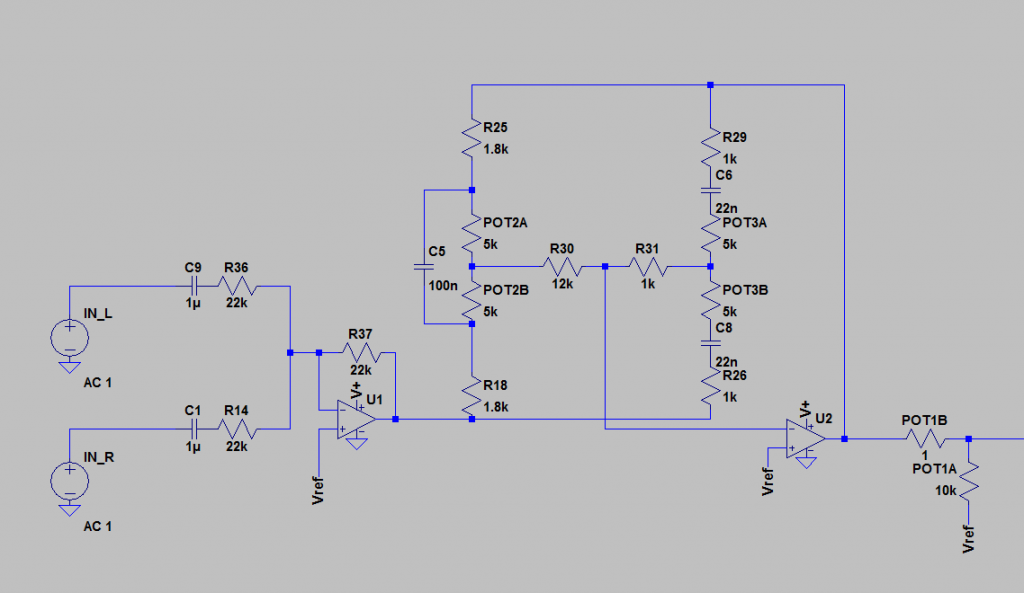
 The stereo inputs are summed by a summing unity-gain amplifier. In retrospect, the input impedance should probably have been chosen a lot higher than 22k, since a lot of cheap media player outputs can have quite high output impedances.
A conventional baxandall circuit (with two HF-capacitors) comes after the summing OPamp, and is used to control the treble and bass response of the amplifier. In essence, the feedback path is divided into two branches for HF and LF.
For bass frequencies, the series capacitors in the right branch will have a very high impedance (22 nF at 100Hz has a 72kohm impedance). This will make the small impedance changes by the right pot not matter much, so the right branch is in essence a unity gain feedback loop att bass frequencies. The left branch capacitor will have a high impedance as well and can be ignored for bass frequencies, which means that the left pot sets the gain of the entire circuit att LF.
Conversely, the 100n capacitor to the left will short out the potentiometer at high frequencies, causing the left branch to be a unity gain feedback loop instead, and the gain for HF is set almost entirely by the right branch.
Following the tone control, a simple potentiometer at the output of the OPamp decides the level that is passed on to the output stage OPamp, to make volume adjustable.
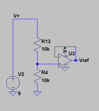
Since the entire circuit operates on a single-ended supply of 9V, we have need for a virtual signal ground at 4.5V. One (bad) way of doing this would be to simply make a low impedance voltage divider to connect all signal grounds to. This would be very susceptible to signal ground currents and can probably cause oscillations where we do not want them. Also, the low impedance required will draw a substantial current, which is bad if we want to say, operate the circuit from a battery. A better way, that I used for this circuit, is to let an opamp voltage follower provide a low-impedance signal ground:
It might be a good idea to have a capacitor in parallel with the voltage division, to remove some thermal noise, as well.
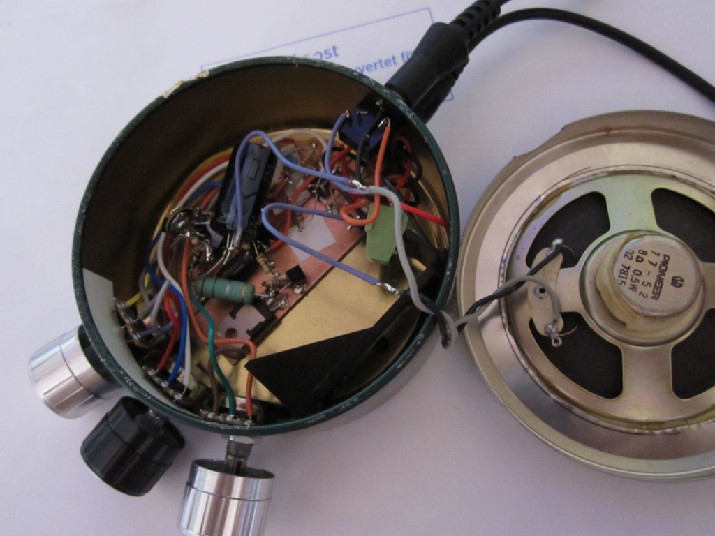
The finished construction is shown below:


