The amplifier is a class-B power amplifier, so each of the two push/pull output transistors will conduct for half the output period, with close to zero static current.
In order to pick a suitable heatsink for the output transistors, it is necessary to do some math to see what the worst case power dissipation is.
Consider the positive supply rail and the upper output transistor. We assume a sinusoidal input with amplitude A, and make the following definitions:
- Voltage over the load:
- Current through the load:
- Supply voltage:
- Voltage over the output transistor:
- Current through the output transistor:
(for the first half of the period)
(for the other)
The average power dissipation of the transistor with time-varying voltages and currents can be expressed using the mean of the energy integral over an output period:
Since our upper transistor will only conduct for half this period, the integral will simplify to this expression:
More simplification:
We split this integral into two and take them on one by one:
And the other:
So the final expression comes to:
We need to figure out which makes for the worst case, so we take the derivative and find the maximum:
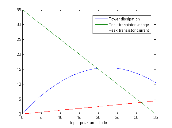
We can see this result by plotting the power function also, along with peak current and voltage through/over the transistor:
Putting this into the power formula gives:
So we see that the upper output transistor has an average power dissipation of 15.5W over an output period. Due to the symmetry of the output stage, the lower output transistor will have the same power dissipation, and the total average power that needs to be handled by the heatsink is 31 W.
The heatsink I chose has the following thermic resistance specification:
1.7K/W @ 40 W
Which means that the temperature increase will be roughly above room temperature in the worst case, which is fairly acceptable.

