One of the problems you are faced with when designing a power supply for a power amplifier is the inrush current of the components. There are two main sources for this phenomena:
- The toroidal transformer – At its initial connection to the AC power grid, the transformer draws initial transient currents of 10-50 times the normal operating current before settling into continuous operation.
- The capacitor bank – Initially the capacitors look like short circuits to ground, limited only by the equivalent series resistance. When connected to the positive supply voltage, this produces a large initial current as the capacitors charge to the supply voltage.
The problem with these large inrush currents, mainly, is that the fuse of the line in the building where the amplifier is used may blow. There are some techniques for preventing this. All involve limiting the current through some kind of resistance, which is gradually removed as the transformer/capacitors settle into normal operation.
One possibility is the use of an NTC resistor (a temperature sensitive resistance). The NTC resistor is connected in series with the primary winding of the transformer. Initially, when the NTC is cool, it presents a significant resistance which limits the inrush currents. As the currents pass through the resistor, it dissipates power which warms the resistor, which in turn decreases the resistance. After a short amount of time, the NTC resistor has warmed enough to not present any significant resistance at all in the path of the transformer current charging.
Another way is to use a normal resistor, and instead use a relay that shorts the resistor terminals after a certain amount of time. This requires the addition of some control circuitry that delays the switching of the relay for about one second after the power grid connection.
My solution
In retrospect, the best idea would probably have been to go with the NTC resistor. As it is, I did a slightly less effective version of the relay inrush suppression. Since having a relay on the primary side would involve running high voltage signals on PCB tracks, I was not very fond of the idea. So instead i built a relay suppressor on the secondary side of the transformer. This means that I only prevent the inrush current from the capacitor bank. Since the transformer I use is not too large, this shouldn’t be too much of a problem.
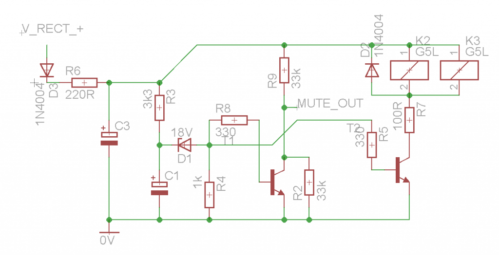
This was done by adding two large 5W, 10 ohm resistors in series with the positive and negative supply, after the rectifier bridge. Over each resistor, a relay was added. The control circuitry for the relays was created by making a small secondary power supply (isolated from the capacitor bank by an additional diode). On this secondary supply, I added an RC-circuit between supply and ground. From the RC node, I attached an 18 V zener diode, which was then connected to the base of the transistor driving the relay inductors. This means that when the RC circuit has charged to roughly 18.7V, the transistor base will see a 0.7V voltage and start conducting, which pulls the switch of the relay, thereby decoupling the series resistances.
The entire circuit was simulated in LtSpice and showed a time constant of roughly 1 second, which gives the capacitor bank just enough time to charge to the supply voltage.
An additional feature of the slow-start circuit is that it can be used to mute the power amplifier inputs while the supply levels are rising. Since the supply is connected to suppression resistors, having two power amplifier channels drawing large currents during startup would never let the capacitor bank charge (and would produce very distorted clipped sound). So the same node that controls the relays is also used to send a muting signal to the amplifier boards.

