Since I only had a single-supply professional lab PSU at home, yet wanted to experiment with OP-amp circuitry and audio amplifiers, the need arose for a symmetric lab supply. Buying a new one (although a decidedly good option in the long term) costs a lot of money, and so I decided to design my own, simple instrument. The idea came partly after experimenting with my audio amplifier that ran on a +-38V unregulated non-limited supply and burning transistors here and there. I felt the need for a lower voltage supply, with current limiting, which shaped the desired specification into the following:
- Variable voltages (single pot controlling both positive/negative side) to allow for gradually increasing voltage and looking for any high currents.
- Voltage levels noncritical, something in the interval +-[0,15]
- Ripple regulation noncritical (OP-amps and audio circuits usually have good PSRR anyway), but still a measure of regulation is desired
- Automatic current limiting (in the range of 1A or so)
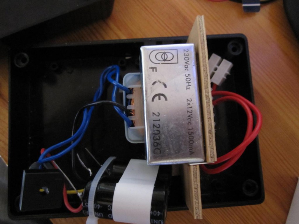
With this in mind I set out to find some components. The mains circuitry was found pretty quickly, a 2×12 VAC , 1.5A transformer was bought and connected to an encased rectifier bridge, with two 4700 µF capacitors for removing the AC components. This would give me an unregulated DC voltage of around 16-17 volts.
Assembled mains circuitry:
Figuring out what regulating circuitry to use was trickier. Most ICs that I found were either quite expensive, or lacking in some respect. I considered using LM317/337 circuits, but since these can only either perform voltage regulation or current limiting, this would require two of them in series per supply side, and since they have a quite hefty dropout voltage of 2-3 volts this would put my regulated voltage at a maximum of around 10 volts. I decided that i atleast wanted to achieve 12 V maximum, so this idea was scrapped.
Another circuit i considered was the old classic LM723, which is in essence a temperature stabilized voltage reference, coupled to an internal OP-amp with pass transistor. External resistors set up a voltage division on the output voltage that the circuit compares to the voltage reference in order to perform regulation. A second internal transistor is used for bleeding base current from the pass transistor in order to perform current limiting. This circuit basically had everything I wanted but for the fact that it could only perform all of its features from a positive supply.
However, since the internal workings were quite easily understood, I decided to adapt the circuit in order to create my own discrete LM723-inspired double-supply regulator.
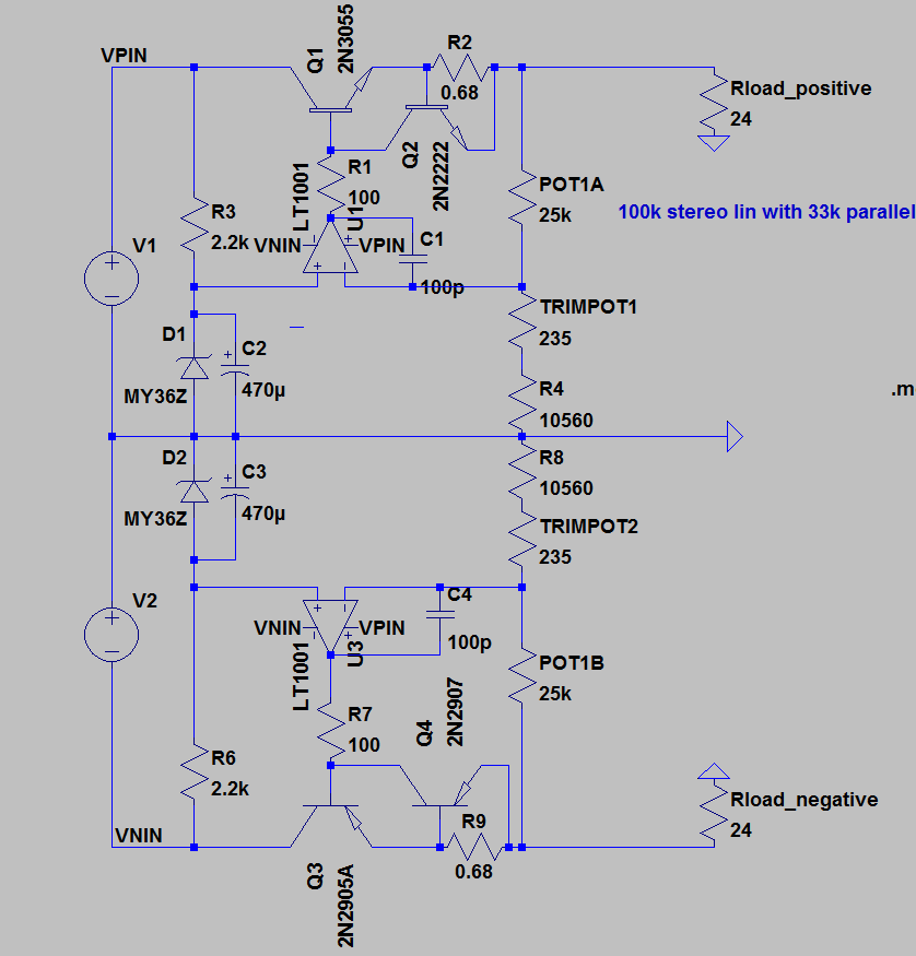
Here is the schematic I came up with (note: don’t mind the component types, I just picked transistors that were similar to mine from those available in the ltspice library):
For the voltage reference I used what i had at home, which was a 3.6V zener diode. This is not very temperature stable, and since it is fed from the unregulated supply will also introduce a degree of ripple into the circuit, but I decided that it would be good enough. A large polarized capacitor at 470µF was added in parallel to attenuate any ripple components over the zener. It should be noted that the reference sets the minimum output voltage, so my output voltage cannot go lower than about 3.7 V.
For pass transistors I used the quite old MJE3055/2955 transistors, mostly just because of the low price. A second transistor with higher gain was added in a darlington configuration to make regulation easier with high currents.
For the OP-amp I picked what I had that could perform under the unregulated voltage of up to +-17 V, which happened to be the audio-grade NE5532. The OP-amp compares the voltage reference from the zener diode to a voltage division on the output. The voltage division is set by a resistor and a potentiometer in order to make it variable. A trimpot is also added to both sides to provide for a way of setting the max voltage to exactly 12V.
The OP-amp also has an output impedance of 100 ohms added, in order let the limiting transistor bleed base current from the pass transistor. The limiter works by having a series resistor in the path of the output current. When the resistor voltage drop exceeds that of the base-emitter junction voltage for the transistor, it starts to conduct, which draws current from the pass transistor, which lowers the output voltage.
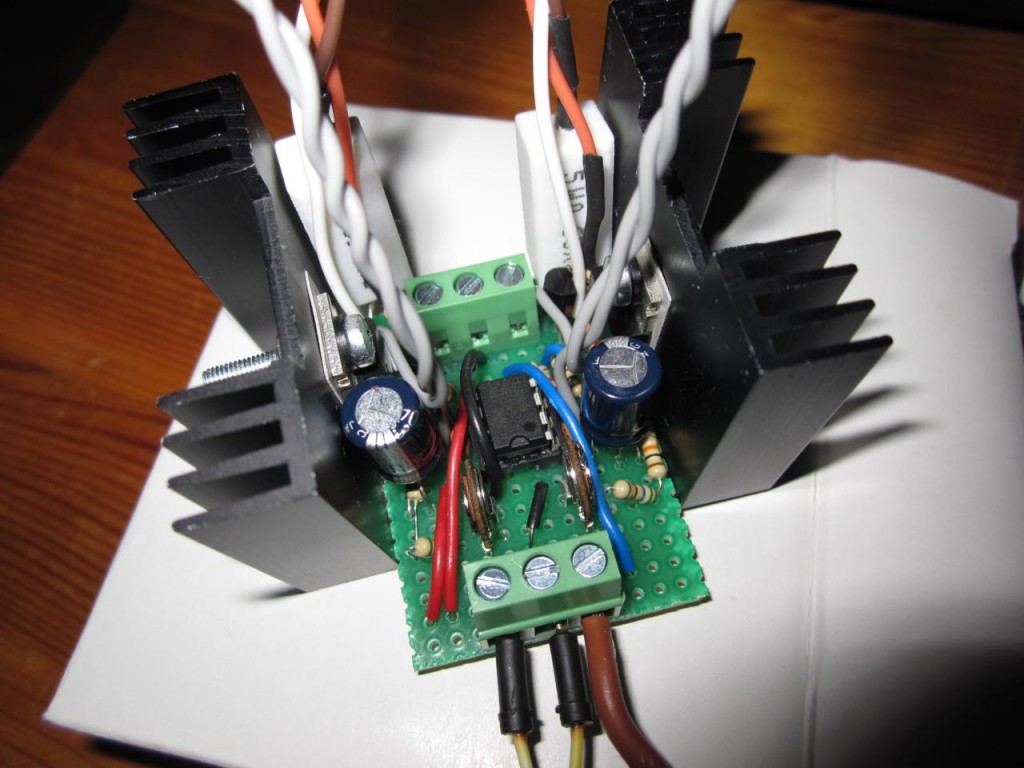
The assembled circuit with some passive cooling clamps is shown below:
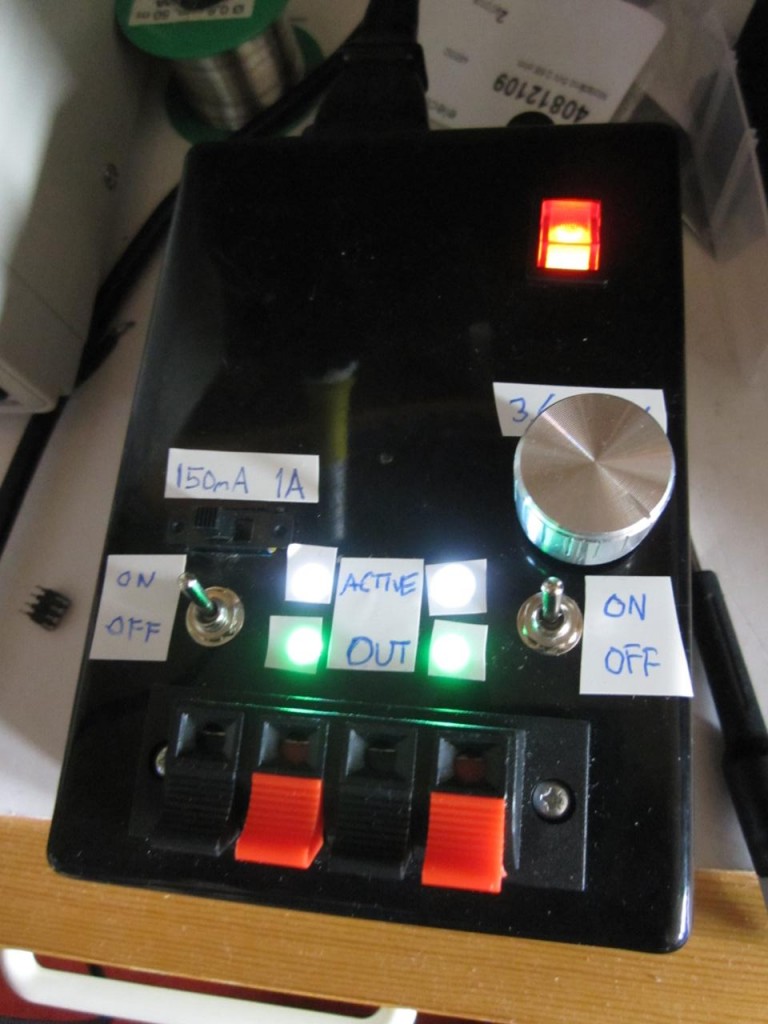
I used a two pole switch to provide two different series resistances, either a 0.68 ohm high wattage resistor, or two resistors in parallel for roughly 4 ohms. This gives limiting currents of approximately 1A and 150mA respectively. For a short-circuit load the output voltage will go all the way down to 0 V, with the pass transistor at worst having to deal with ~16V, 1A => 16W power dissipation.
The finished box is shown here:
For ease of use I also added some LED indicators to the casing (these help show when there is a short-circuit, since the output voltage goes down to 0V and the LEDs go out), and also some switches for turning on/off each supple side separately.


