This project page details the construction of a switching driver with adjustable intensity through PWM, for a 3W RGB power-LED.
Each channel of the LED is specified at 350 mA working current, with roughly 2.5 V forward drop for the red diode and 3.5V for the blue/green ones.
When using RGB-LEDs, a simple resistive current limiting scheme will be highly inefficient. An example calculation of the power loss from a resistive limiter when running the red diode from a 5V supply is:
For three channels with roughly the same specs, we get a heat dissipation of about 2.5 W, which is almost as high as the actual power rating of the LED. Not so power efficient.
The obvious solution to this is to use a switch-mode driver instead. A buck-converter that does a DC-DC conversion to the appropriate forward drop voltage will only see slight losses in the switching components.
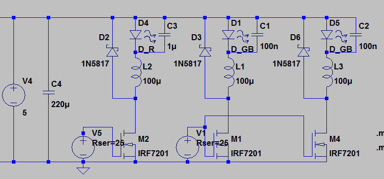
A sketch over a switching RGB-LED driver is shown below:
Let us take the red channel as an example. When the MOS-transistor is turned on, the node above it is effectively grounded. If we assume that the current through the LED at turn-on time is , and that the voltage over the diode is at a constant 2.5V, we can use the formula for the inductor current/voltage relationship:
We can see that the current increases linearly with time, with a derivative that is inversely proportional to the inductor value.
Once the transistor is shut off, the schottky diode will conduct the current instead, and we get a different equation. Assuming the schottky diode has a constant 0.5V voltage drop:
Now, the problem for the driver is, how do we generate a good PWM-signal that keeps the ripple caused by these two equations small, around a DC component of 350 mA?
One pretty obvious solution is to somehow measure the current and use the microcontroller to stabilize it using a PI-regulator. This could be done by having a small resistor in series with the path of the current, A/D-converting the voltage over it using an µC-A/D-channel. This presents some problems, two of which are pretty significant:
- My RGB-LED had a common-cathode configuration, and thus any current measurement would have to be done with respect to the +5V supply, or differentially.
- Any software-failures might result in a constant high signal to the MOS input, which would cause the current to increase until the LED is destroyed.
Some consideration around these points led to an implementation that relies more on analog circuitry and less on the µC-software.
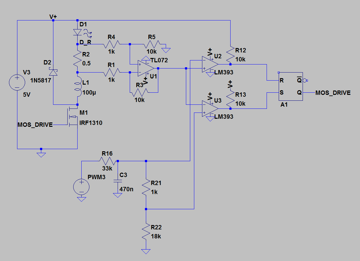
The following schematic illustrates the control circuitry for one channel:
 Resistor R2 measures the current through the LED. OPamp U1 is connected as a differential amplifier, and converts the voltage over R2 to a single-ended voltage with respect to ground. It is important to note that R2 is placed below the diode and above the inductor. This makes certain that the voltages around R2 will always be around halfway between the +5V supply and GND. This is important due to the fact that many cheaper OPamps are created to only function with input common mode levels from ground up to about1.5V below Vcc. Placing R2 in this way removes the need for a more expensive OPamp.
The result is a voltage of roughly 0-1.75 V for LED currents of 0-350mA. This is where comparators U2 and U3 come in. They each take a reference voltage and compares the current-measurement-voltage to this reference. Their outputs are fed into an S/R latch in order achieve an on/off-hysteresis. The result is that whenever the current gets too high, U2 resets the latch, shutting off the transistor. When the current goes too low, U3 sets the latch, turning on the transistor.
The reference voltage is taken from an RC-filtered PWM output from the microcontroller. In order to make the circuit safe from software errors, a voltage division is done so that a constant high automatically gives a reference that makes the LED-current near 350 mA.
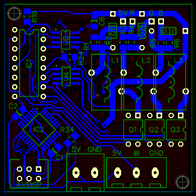
I designed a PCB after this schematic, which is shown below:
- OPamp: 1x LM324, a quad opamp which is capable of operating with input common-mode at ground.
- Comparators: 3x LM393, a dual comparator package, which also can handle near-ground signals
- MOS: 3x HEXFET IRLD120
- µC: ATmega88
- Schottky: 31DQ04
- Inductors: 100µH toroids
- S/R-latch: CD4043


